|
Photo Gallery
Evaluation
of a J.F. Breton Violin
|
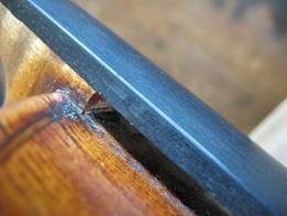
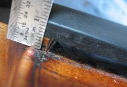
Fig. 1 |
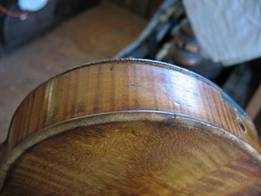
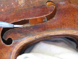
The photo in Fig. 1 reveals a shim inserted under the fingerboard between the neck block and the top. Also evident in this photo are top cracks running parallel to the grain. This may have happened when the table (top) was separated from the upper block. In repair terminology, the inserting of a shim here is called a neck slip. It is a standard procedure performed if fingerboard projection is low evident in the string height or playability. At times, this is the correct choice of repair. |
|
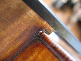
Fig. 2 |
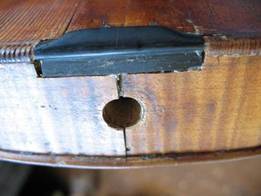
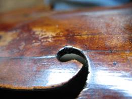
In Fig. 2, top wood is left attached to the side of the neck when neck assembly (neck, upper block, ribs) is tipped back and away from top to insert shim as previously mentioned.
|
|
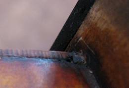
Fig. 3 |
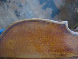
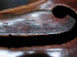
Fig. 3 confirms top wood replaced at neck join. Also visible, is no relief between the ribs and top edge along the upper bout where the neck was tipped back when it was slipped (refer back to Fig. 1). |
|
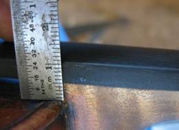
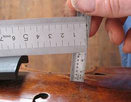
Fig. 4 |
Height of neck overstand above E-side mortise; the modern standard is 5 to 7mm. |
|
Fig. 5 |
Fig. 5 is measurement of overstand above G-side mortise. |
|
Fig. 6 |
Photo in Fig. 6 displays fingerboard projection at determined bridge placement of 26+ mm, however, because of the severity of the over pitched neck and increased string tension as a result from it, centering and correction of the neck angle is desirable. |
|
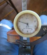
Fig. 7 |
In Fig. 7 shows a caliper reading of the neck/fingerboard thickness measured nearer the handle at 18mm. |
|
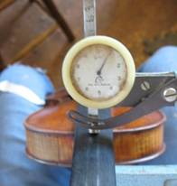
Fig. 8 |
Fig. 8 shows a caliper reading taken nearer the corpus (body) at 21mm, revealing a disproportionate neck. |
|
Fig. 9 |
The photo in Fig. 9 is of an unevenly distributed L-lower rib with little relief between rib, top and back edge. |
|
Fig. 10 |
Fig. 10 shows a photo of loose ribs pulling away from the end block and saddle as well as previously repaired open top cracks . |
|
Fig. 11 |
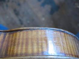
In Fig. 11 reveals where the edge of the table (top) has worn beyond the rib join along the R-upper bout. |
|
Fig. 12 |
Fig. 12 shows top view of worn edge at R-upper bout. R-upper corner has considerable wear, as well. |
|
Fig. 13 |
Fig. 13 reflects mirror image of just one of many softwood cleats glued along belly cracks throughout table. |
|
Fig. 14 |
Fig. 14 shows to a greater extent the misaligned F-hole crack and soundpost region. |
|
Fig. 15 |
Fig. 15 is a photo of an open wing crack. |
All web content copyright Davenport Violin & Bow
